Introduction
The RMC is a decentralised control unit that ensures that the installations are switched on and off at the correct time. It also checks the correctness of the supply in real time by reading the energy meters. Installations are for instance a CHP or lighting of a greenhouse.
History
The first version of the RMC was developed in 2006. The RMC consists of a controller (Single Board Computer) with a simple Linux operating system and ICPDAS I/O modules. We had to assemble everything ourselves in a standard rittal box.
RMC V1 had to be custom made. This required several visits for an installation. The installations also ran long regularly, so we had to reserve extra time around the installation days.
In 2010, we started developing a new version that was to become a kind of box of blocks. The goal: inventories should no longer be necessary and the installations had to run faster. We developed our own controller and IO module for RMC V2. In practice, we could now do one to two installations per day.
Functions
Energy meters
Pulse contacts or Modbus counters are used to measure energy. The standard measurement time is one minute. The measured data is stored locally and sent to EnetControl for further processing.
Controls
EnetControl sends control schemes to the RMC. The RMC translates these schemes into hardware signals that operate the physical installations. As a result, the physical installation is started, stopped or modulated to a specific capacity at the right time. This control is done via simple contacts and/or analog signals of 0-10 Volt or 4-20 milliampere.
Architecture
The RMC consists of a controller that is connected to the internet and has one or two RS485 buses for communicating with the I/O modules . I/O modules can be ICPDAS-I7000 or standard MODBUS-RS458. We chose RS485 because it only requires two wires, which can be used over distances of up to a kilometre, without special cables.
Controller software
The software in the controller is written in C++. The application consists of several programs that communicate with each other via shared memory.
Program:
| name | description |
|---|---|
| rmccom | Communication with ENetControl via a custom UDP protocol. Via this protocol, measurement data is exchanged, energy schedules received, Linux syslog uploaded and the time synchronised. |
| rmcdacbus | Communication with the I/O modules via the RS485 buses. It supports two different protocols: ICPDAS-DCon and MODBUS-RS485. |
| rmcdata | Saving measurement data. It uses its own special database format, which drastically limits the number of writes. This is to guarantee the lifetime of Compactflash/MicroSD. |
| rmclogic | The control logic. The energy scheme is translated into various output signals, both digital and analog. Power monitoring is possible so that the physical connection is not overloaded. |
| rmcctl | A command-line utility to read real-time data from the various programmes. |
I/O Module
We developed our own digital I/O module for the RMC-V2. The heart of this module is the ATMEGA16A. That is an 8-bit RISC microcontroller with 16 KB of programmable flash memory and 1 KB of SRAM that is programmed in C. Communication with the controller is through the Modbus-RS485 protocol. It was necessary to program everything ourselves: interrupt handlers, read out input signal, debouncing inputs, counting pulses, logic and modbus protocol. Everything had to fit into 16 KB. The final image was slightly larger than 6K.
Hardware
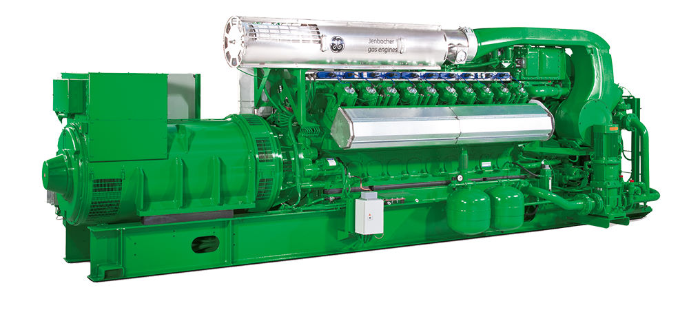
Version 1
Hardware
- Arbor I612 SBC
- Intel Ultra Low Voltage Celeron 400MHz processor
- 64 MB Memory
- 265 MB CompactFlash
- Openframe mini PC power supply (-5v,-12V,5v,12V)
- ICPCON 7520R RS232 <=> RS485
- ICPCON I/O Modules
Software
Linux image build from source files (Linux From Scratch) with root filesystem of 14 MB.
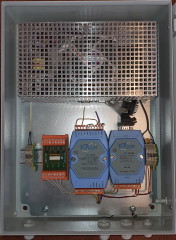
Version 2
Hardware
- Self-developed controller based on Taskit PortuxG20 with a self-developed PCB for power and RS485
Taskit PortuxG20:- Atmel AT91SAM9G20 with ARM926EJ core at 400 MHz
- 64 MB Memory
- 2 GB MicroSD
- Standard 12v power supply
- Self-developed 8DI/DO module
- Optional: ICPCON I/O Modules
Software
Embedded Linux image using OpenEmbedded framework
Developed hardware
For the RMC version 2, we developed our own hardware using, among others, Autocad Eagle
CPB - CPU Power Board
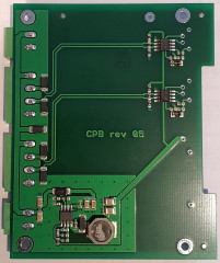
CPB is a simple sign to power the PortuxG20 with 12V and to convert the TTL signal from the PortuxG20 to RS485.
- Step-down converter for converting 12V to 5V
- 2x RS485 converter to TTL
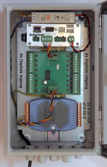
DIO - Digital I/O
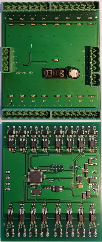
A board for digital input and output, with eight digital inputs and eight digital outputs. In addition to the actual values of an input, each input has a 32-bit pulse counter. In order not to have false input pulses, de-bounced is done throuigh the software. In addition to a digital output that can be set via the modbus, you can also link it to an input. This way, the input is passed on as a pulse to the output. This is often used to transmit energy pulses to another system.
- ATMEGA16 microcontroller
- Eight digital inputs with 12V supply, suitable for potential free contacts
- Maximum pulse frequency 50 Hz
- Eight digital outputs, potential free
- All inputs, outputs and modbus are protected against overvoltage
Technologies
C++, Linux, Modbus, Autocad Eagle,
Production
2005 - 2015
My function
Everything developed completely in-house: functional design, hardware development and software development.